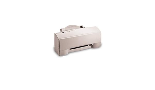
| Uploader: | Kegis |
| Date Added: | 26 June 2008 |
| File Size: | 66.53 Mb |
| Operating Systems: | Windows NT/2000/XP/2003/2003/7/8/10 MacOS 10/X |
| Downloads: | 97176 |
| Price: | Free* [*Free Regsitration Required] |
Remove the two screws securing the paper feed motor and remove the motor. The print cartridge contains single-unit customer-replaceable supply items.
Carrier Transport Page 71 Page 72 - Assembly 7: Cleans the printhead nozzles during the print operation.
If two assemblies contain a majority of identical parts, they are broken down on the same list. High-capacity output stacker installation instructions 98 pages. The test page will contain the following: Be sure the short extensions of the two paper flap springs are trapped under the carrier frame [C]. Also check the paper for curl or wrinkles.

Slide the cover forward and off the printer. Remove the four screws [A] securing the carrier frame to the left and right side frames and remove the carrier frame assembly.
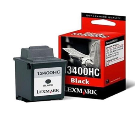
Lexmark JetPrinter Color Ink Cartridge - Pages
Be sure the envelope guides are against the envelopes. Install the wrap plug in the parallel port before you start the test.
Slide the cover over the matching pieces on the bottom cover. Connector Locations X, 30X 5.
Parallel Port Test X, 30X Parallel Port Test This test performs a wrap around test between the printer parallel port and the parallel port test connector. Carrier Transport Motor Removal 1.
Make Your Selection
This ejtprinter also for: This test requires a parallel port wrap plug. Symptom Tables X, 30X Symptom Tables Locate the symptom in the following tables and take the appropriate action.
Adjustments X, 30X Adjustments The user is directed, in the Printer Control program, to perform the head to head and bidirectional alignment adjustments after replacing a print cartridge.

Removal Procedures The following procedures are arranged according to the name of the printer part discussed. The Busy light reflects the paper sensor status in the following manner: Preface X, 30X Preface This manual is divided into the following chapters: Remove the paper load door and manual insert tray. Repair Information X, 30X 4. Remove the base assembly.
Table of Contents Add to my manuals Add. Gently pry the Code Module from the system board noting the position of the notch in the module. Remove the retainer from the right end of the carrier guide rod. Online user's guide for mac os x Check for 8 to 18 ohms between pins 2 and 3 on the motor cable. Dual printheads provide color and true black printing without changing printheads.

Comments to this Manuals Your Name. Be sure the cable is secured under the three retaining clips [B] on the back of the carrier.


No comments:
Post a Comment